Content
Needling Techniques
Click on an item to jump to that section.
- Basics and needle properties
- Methods of ultrasonographic needle guidance
- Visualization of the target structures
- Methods of improving US needling techniques
- References
Basics and needle properties
Needles have peculiar characteristics when viewed using ultrasound waves. In order to study these characteristics, it is customary to study needles immersed in water baths. Many of the characteristics exhibited by needles in water baths are not clear or visible in biological tissues, because biological tissues are composed of a heterogeneous mixture of fat, connective tissue, muscle and blood, all having a significantly higher echodensity than that of water. However, it is helpful to realize needle properties to better judge the ultrasonographic images in the various biological tissues.
Reverberation results when the sound waves keep getting reflected back and forth between two parallel smooth surfaces, with some sound waves reaching the probe at each cycle of reflection. This is displayed by the ultrasound machine as several 'copies' of the same object. Figure 1 shows reverberation of sound waves when the beam is directed along the long axis of a hollow needle. Reverberation occurs within the core of the needle, resulting in the appearance of 'several needles' in the ultrasound image. The true needle is the one closest to the ultrasound probe (the uppermost one). Reverberation may not be so obvious in biological tissues, but if it is seen, it should be interpreted correctly.
Demonstration of Reverberation
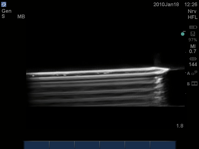
Figure 1. Reverberation of the sound beam within the core of a hollow 17G Tuohy needle immersed in a water bath resulting in the typical reverberation artifact beyond the needle.
Air bubbles reflect almost all ultrasound waves, resulting in a shadow distal to the air bubble, effectively obscuring other tissues/details. Figure 2 shows a 17G Tuohy needle with an air bubble at its tip. Note the shadow distal to the air bubble, effectively obscuring part of the tip of the needle. Practically speaking, air bubbles within needles should be avoided to enhance the US image.
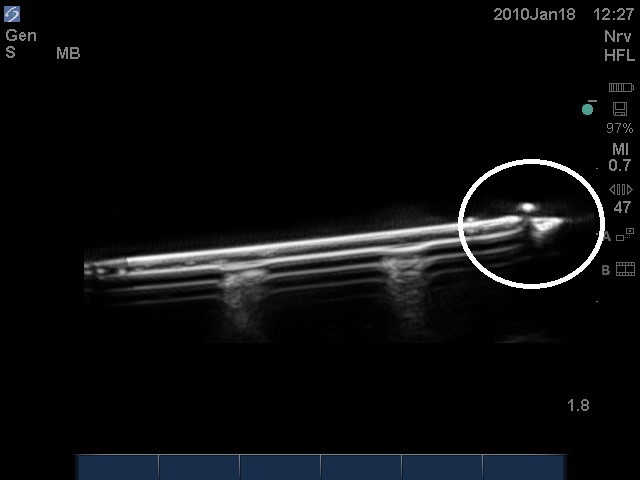
Figure 2.An air bubble at the tip of the needle (white dot), with a distal shadow, effectively obscuring part of the tip of the needle.
Scattering of ultrasound waves, when they hit non-planar surfaces, results in a distorted image. This is especially seen in a transverse section of the needle and is illustrated in Figure 3, where the presence of lateral shadows of the needle is observed. A similar, familiar light scattering pattern (when the light source is seen in a foggy night) is also shown in Figure 3 to visually illustrate this kind of artifact more.
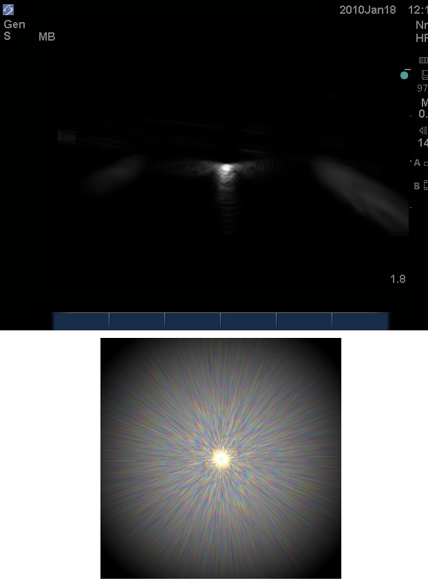
Figure 3. Scatter artifact shown as the white lateral glow next to the needle (top). A similar, familiar pattern of light scattering (bottom).
Methods of ultrasonographic (US) needle guidance
Indirect US guidance
The target structure is localized prior to puncture using US. The skin is marked and the angle and depth of the needle course are estimated. Imaging is then abandoned and the needle is directed toward the target tissue. Indirect US guidance is likely to be safer than pure landmark techniques as it identifies the approximate position of a suitable target structure, e.g., ligamentum flavum/dura unit in ultrasonographic guidance of spinal/epidural insertion. It also helps when the landmarks are difficult to palpate or identify (impalpable spine in obese patients), or when they are distorted (spine surgery). However, it is only really appropriate when neither precise needle placement nor avoidance of collateral structures apart from the target is mandatory.
Direct US guidance (real-time ultrasonographic guidance)
US identifies the target structure and then it is used to visualize the needle in real time as it traverses through the tissues and guide it to precisely penetrate or lie alongside this, as necessary. Collateral structures can be deliberately avoided. Real-time scanning techniques produce a rapid series of images, which are displayed sequentially to depict motion giving a real-time, two-dimensional image of a three-dimensional structure.
Ultrasound techniques demand thorough knowledge of the regional anatomy to identify surrounding structures and interpret images when seeking out target membranes, vessels and nerves. The operator's skill in aligning the US probe and needle is arguably the most important variable influencing needle visualization, and considerable real-time scanning experience remains the key factor to the successful performance of ultrasound-guided interventions.
In-plane needle approach
The needle is inserted parallel to the US beam and the shaft of the needle is seen as an echogenic white line (Figure 4). Alignment of the ultrasound beam and the needle in this approach is the major key to success, and it takes a lot of practice to master. The target structure is usually placed to one side in the ultrasound field, and the needle is advanced from the other side towards the target, usually at an angle of 45° or less.
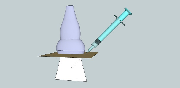
Figure 4. In-plane needle approach.
The major advantage of this approach is that the needle tip is identified more easily. However, the needle course is seen only in relation to the target of interest and not in relation to adjacent (lateral) structures, which are outside the ultrasound beam in this approach. If the needle approach is made steeper the image will degrade.
The main cause of a 'disappearing needle' in this approach is by far misalignment of the needle with the ultrasound beam. If the needle disappears, alignment should be checked by inspecting the needle and the probe and moving the probe to regain alignment. Movement of both the needle and the probe at the same time should be avoided. Advancement of the needle without visualization of the needle tip is strongly discouraged.
Factors that might result in misalignment include improper handling of the probe and operator fatigue. The probe should be held with one or more fingers of the holding hand resting on the patient to stabilize the probe and avoid unintentional sliding (Figure 5). Attention should be paid to ergonomics when performing US-guided procedures to avoid operator fatigue.
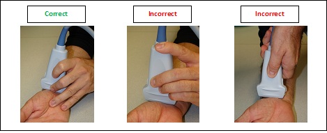
Figure 5. Correct (left) and incorrect (middle and right) methods of holding the ultrasound probe. Not having an 'anchor' to the patient can result in unintentional sliding of the probe.
Opponents of the in-plane needle approach argue that it is more time consuming; that the partial line-up of the needle and the probe create a false sense of security; that it is not always practically feasible to align the needle, the probe and the target structure; and that the technique requires longer needles, which may add to the discomfort of the patient.
Out-of-plane needle approach
The needle is introduced perpendicular to the plane of the ultrasound beam (Figure 6). Typically, vessels and nerves are viewed in cross section, enabling adjacent structures to be easily visualized, but this approach gives poorer visualization of the needle because, first, the angle of approach of the needle is more parallel to the ultrasound beam, and second, only one short segment of the needle is visible. What is thought to be the tip of the needle may actually be the needle shaft.
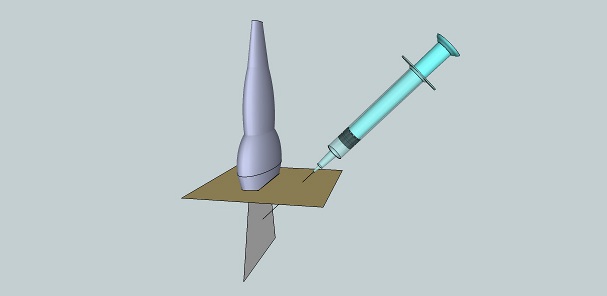
Figure 6.Out-of-plane needle approach.
There are two techniques that can be used to aid in correct needle placement, i.e., the small-volume injection test (also called hydrodissection or hydrolocation) and the "walk-down" method. In the small-volume injection test (which can be used with either in-plane or out-of-plane approaches), what is thought to be the needle tip is centered in the ultrasound image, and injection of a small amount of a clear solution enhances the view of the needle tip by producing a bigger difference of echodensity between the injected solution and the needle tip, as opposed to the difference between the needle tip and the surrounding echogenic tissue (Figure 7). Injection of microbubbles is highly discouraged, because they 'cloud' the view, obscuring underlying tissues.
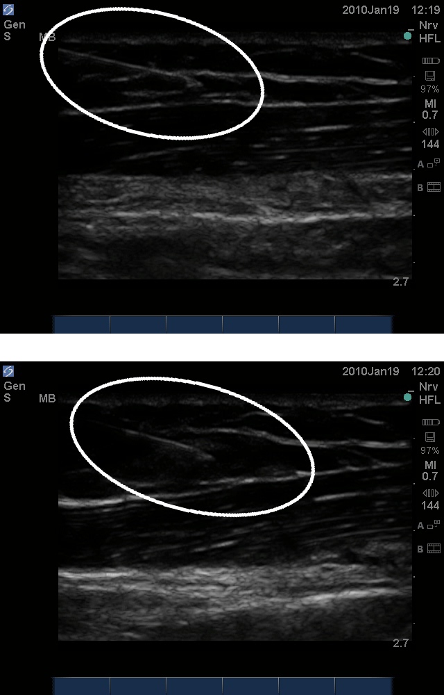
Figure 7. Hydrolocation in the in-plane approach. Top: A 20G needle advanced through soft tissue from left to right. Bottom: Injection of 1.0 ml of normal saline displaced the soft tissue at the tip of the needle and enhanced its visualization.
The "walk-down" method is used with the out-of-plane approach and it uses the US to determine the depth of the target structure. The puncture site is chosen to be of equal distance from the probe as the target depth. The needle is then inserted at a shallow angle and advanced until the tip is identified. Then, the needle is tracked at progressively steeper angles until the target is reached at approximately 45° (Figure 8). Geometrically, at 45° the needle, ultrasound beam and skin will form an isocele right triangle with the depth equal to the distance from the probe.Inserting the needle at a steep angle (about 75°) to the probe in the out-of-plane approach is also a technique advocated by many. Visualization of the needle tip has been proven to be better with steeper angles in this technique. There is no single most advised method to handle the needle in the out-of-plane technique. Reliance on surrogate measures and other methods of enhancing needle visibility can help.
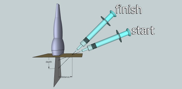
Figure 8. The walk-down method in the out-of-plane needling approach.
Visualization of the target structures
Long-axis view
The ultrasound probe is placed so that the ultrasound beam is parallel to the long axis of the target structure. For vascular structures, color Doppler can be used to identify arteries versus veins. Figure 9 shows the long axis view of the carotid artery, internal jugular vein and radial artery. Figure 10 illustrates both the in-plane approach and the out-of-plane approach in a long-axis view of a target structure.
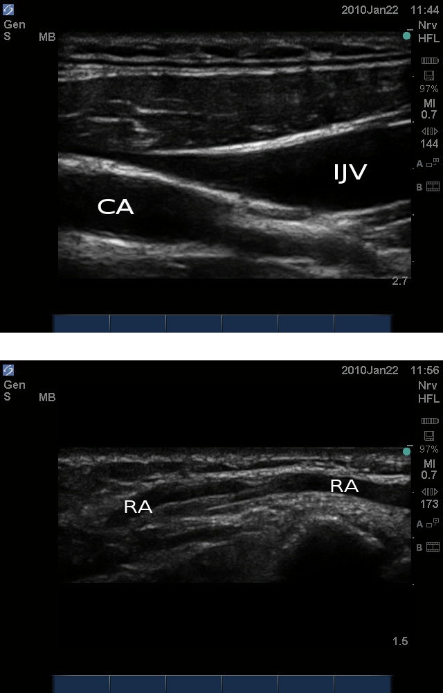
Figure 9. Top: Long-axis view of the carotid artery (CA) and internal jugular vein(IJV). Bottomg: Long axis view of the radial artery (RA).
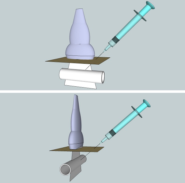
Figure 10. Illustration of the in-plane (top) and out-of-plane (bottom) approaches in the long-axis view.
Short-axis view
The ultrasound probe is placed so that the ultrasound beam is perpendicular to the long axis of the target structure. Color Doppler can also be used to differentiate veins from arteries. Figure 11 shows the short axis view with color Doppler of the carotid artery, internal jugular vein and radial artery. Figure 12 illustrates the in-plane and the out-of-plane approach in a short-axis view of a target structure.
Methods of improving US needling techniques
Simple practical techniques
- Larger needles are more easily visualized than smaller ones.
- Directing the ultrasound beam perpendicular to the needle rather than parallel to it
- The use of styleted needles if possible decreases reverberation artifact.
- Filling the needle with a clear solution rather than air.
- Introducing the needle with its bevel either pointing towards the ultrasound probe or away from it. The relatively rougher bevel results in more ultrasound scatter, enhancing the tip.
- Tissue movement: introducing the needle in a short "in-and-out, side-to-side" motion causes deflection of the adjacent soft tissues and makes the trajectory of the needle more discernible.
- Hydrolocation: injecting a small amount of a clear solution can enhance the visibility of the needle tip.
The use of special needles
Several trials have been made to manufacture special needles with increased echogenicity to increase ultrasound reflection at the interface between needles and tissues. A needle has been designed with special echogenic markings near the tip of the needle that appear as bright dots on the ultrasound screen. Certain needles have a stylet with a piezoelectric crystal at its tip to receive the ultrasound beam. The stylet is wired to the ultrasound machine, which is programmed to display the piezoelectric tip as bright red on its screen.
References
- Carvalho JCA. Ultrasound-facilitated epidurals and spinals in obstetrics. Anesthesiol Clin 2007; 104:1188-92.
- Chapman GA, Johnson D, Bodenham AR. Visualisation of needle position using ultrasonography. Anaesthesia 2001; 26: 64-7.
- Chin KJ, Perlas A, Chan V, Brull R. Needle visualization in ultrasound-guided regional anesthesia: Challenges and solutions. Reg Anesth Pain 2002; 14:169-75.
- Tsui BCH, Dillane D. Continuing medical education: Ultrasound guidance for regional blockade – basic concepts. Can J Anesth 2001; 13: 213-17.
Endnote
Ultrasound images were produced using SonoSite M-Turbo™ ultrasound machine with HFL38x/13-6 MHz transducer.
Needles were immersed in a water bath to illustrate needle properties.
Ultrasonographic images of hydrolocation of the needle tip were scanned from a live model.
Special thanks are due to Dr. José Carvalho for reviewing the text, and to Dr. Cristian Arzola for helping with preparation of the images.